Updated June 2018
Variometer – a fast response rate of climb instrument usually scaled to match typical glider rates of climb and descent.(+/-10 knots or +/- 5 meter/sec). The variometer makes soaring possible by displaying the glider rate of climb to the pilot in near real time, enabling the pilot to manoeuvre the glider so as to remain in rising air. Variometers come in many types, some sense the airflow from a capacity bottle or chamber (as the outside pressure increases or decreases due to altitude changes, air flows in or out of the chamber to equalise the pressure) either mechanically or electrically, others measure the air pressure directly using silicon pressure transducers and compute rate of climb electronically from the changes measured. All Borgelt variometers since 1982 use this last method. Audio signals which vary with rate of climb/descent are also possible when electronic sensing is used and this is a great help in keeping pilots looking outside the cockpit for other traffic, gliders or birds climbing better in nearby thermals and interesting and/or useful meteorological phenomena. In turbulent thermals while our variometer will help us find the best lift, it is sometimes difficult to know how fast we are really climbing (or whether we really are climbing) as there may be sink in part of the circle and lift in others. In this case we can use an AVERAGER which is really just a slow response variometer. Most vario averagers average the variometer readings so that the running average rate of climb of the last circle or so is shown. This requires averaging over 20 to 30 seconds. The averager display may be “on demand” or continuously displayed in digital form.
It is also possible to have another type of “averager” more correctly called an INTEGRATOR which, in a thermal, shows the average since entering the thermal until the present time. This is NOT the same as a running 20 second averager and this number will be the one to determine your average cross country speed.
TOTAL ENERGY Variometer – the basic variometer described above suffers from the effect that as the glider changes airspeed in response to pilot inputs, large transient rates of climb and descent are induced until the airspeed is stabilised at a new value. These may easily exceed and swamp the rates of climb due to airmass rising and falling (a 30 degree pullup from 100 knots gives an initial rate of climb of 50 knots, causing the +/- 10 knot scale variometer to indicate uselessly at the top of its scale). If, instead of sensing the outside air pressure or STATIC pressure with the variometer, we connect the variometer to a venturi of the correct dimensions we find that as long as the airspeed is constant the pressure in the venturi decreases and increases as in the basic variometer case. If the airspeed decreases due to a pullup the suction produced by the venturi will decrease and will compensate for the reduced static pressure from the climb resulting in no net change of pressure and hence no change in variometer reading. The suction produced by this venturi (pressure below STATIC pressure) is the same as the pressure increase above static pressure measured by a PITOT tube (open ended tube or hole directly facing oncoming airflow) at the same airspeed. For the last 25 years the most common and best “venturi” in fact doesn’t look like a venturi at all. A 6mm tube usually extends from the fin leading edge and and is bent up or down 70 degrees or so, so that the last 80mm of the tube is at 20 degree forward inclination to the airflow. The end of the tube is sealed and the end is cut off square to the tube (NOT parallel to the airflow) and two small holes are drilled in the rear half of the tube as pressure ports. The suction of the device depends on the distance of the holes from the end of the tube. This design is relatively insensitive to yaw (sideslip) and pitch and unlike a real venturi doesn’t provide a home for spiders and insects. It is also easy to keep clean (required for correct functioning). As it was invented by Frank Irving it is known as an IRVING tube. The generic term for all venturis, probes etc is TOTAL
ENERGY PROBE or TE Probe. A Total energy variometer as described above can be further improved. As described the vario will,in still air, show the glider sink rate at the speed being flown. Let us take a good modern glider such as an 18 meter racer. The unballasted polar curve for this glider will show a minimum sink rate of around 1 knot at around 45 knots IAS, a best L/D of about 50 at around 55 knots and sink rates of about 2 knots at 75 knots and 4 knots at 100 knots. The sink rate through the airmass at typical thermalling airspeed and bank angle will be about 1.6 knots. Now suppose you are cruising between thermals and you encounter rising and sinking air and you vary the airspeed according to Macready speed to fly theory between 60 knots and 110 knots as you encounter rising and sinking air. The vario is TE compensated so changes in airspeed don’t cause large transient indications on the vario. However at 110 knots the glider might be sinking through the airmass at 5 knots and at 60 knots at just over 1 knot. These sink rate changes can mask small changes in the airmass and make it difficult to pick the best path through the air.(which is the path with the most and fastest rising air and the least and slowest sinking air). If encountering a thermal at high speed you may even reject the thermal that is really acceptable. A thermal rising relative to the ground at 8 knots will show as 3 knots up on the vario if you are sinking at 5 knots at 110 knots IAS. In fact after you reduce speed and turn in this air you would climb at 8 – 1.6 = 6.4 knots so it is difficult to use the vario indication to decide whether to accept or reject the thermal being flown through.
A NETTO or AIRMASS variometer adds to the raw TE vario reading an upward deflection to counteract the sink due to the glider polar at that airspeed. Now, in still air, the vario will read zero at any airspeed if the polar we have assumed is correct. Even if it isn’t the differences are likely to be small fractions of a knot and it is much easier to use the vario to pick the best path through the air. There is one disadvantage and that is if we fly through our thermal rising at 8 knots relative to the ground we see 8 knots on the NETTO vario regardless of the airspeed we are flying at. When we slow to circle we climb at 8 – 1.6 = 6.4 knots. So we mentally must subtract our circling sink rate of 1.6 knots to see what rate of climb we will get if we circle now. This is much easier than with our raw TE vario but still adds to workload (for most gliders 2 knots is in fact close enough for practical purposes).
The RELATIVE NETTO variometer is a further refinement of the NETTO vario and is sometimes called just RELATIVE or SUPER NETTO. If we superimpose a downward deflection of 1.6 knots on our NETTO variometer we can see that at any airspeed the variometer will show the rate of climb we will get if we circle. This now makes it very easy to use the vario to decide if the thermal is good enough (it isn’t the only criterion – you may not have flown through the center – you may already be low etc) but at least the vario is easy to interpret. For picking the best path through the air the RELATIVE vario is almost as good as the NETTO. Any time that the vario is heading in the upward direction the air is getting better, downwards worse. To get the best of both the NETTO and RELATIVE vario just mark the 2 knots down position on the outside of the scale with a sliver of white tape. This serves as the “still air” reference point. Any time the vario is above this point the airmass is rising. Do we care about this? Surely we just want the best air? Sometimes it is important in interpreting the meteorology to know if the air is rising or sinking. Also our estimate of how well the glider will go on final glide depends on knowing the absolute rise or fall of the air we fly through. We may be flying in the best available air but if that airmass is sinking at only a fraction of a knot on average we must allow extra altitude for final glide. Earlier in the article I mentioned Macready speed to fly theory. Depending on the anticipated strength of the next thermal and the glider polar and the air you are currently flying through there is an optimum indicated air speed to be flying at. A table of speeds is one way to do this, a moveable scale (MACREADY RING) around the vario is another. If we have the electronics to measure our airspeed to provide a NETTO (or RELATIVE) vario we can also use a little more processing to provide a zero reader for the optimum speed to fly. Pointer above zero – pull up, reduce speed. Below – push and gain speed. This is known as a SPEED COMMAND VARIOMETER or SPEED COMMAND. Audio signals for “fly faster” and “fly slower” may also be generated. This combines the TE variometer reading with a downward offset controlled by the MaCready or STF (Speed To Fly) selector (may be a rotary knob or controlled by accessing a menu on screen) and an upward deflection that gets larger as airspeed is increased. If done correctly the result is that you fly at the optimum speed at all times. For reasons given in the Horizontal Gust article the speed changes should be made gently so the zero reader indications are usually filtered to slow down the commanded changes.
In the current Borgelt variometers the B300, B400, B700 and B900 are variometers and become Total Energy variometers if a TE probe is used as the pressure source. They also have audio and either a push button on demand averager or a full time digital averager. In addition the B700 (logarithmic scale) and B900 (linear scale version of B700) have an INTEGRATOR function and the digital display may show either running AVERAGE or INTEGATOR on pilot selection. These two numbers are also compared automatically as a rinning AVERAGE bleow the INTEGRATED average means the latter is getting smaller and it may be time to consider leaving the thermal.
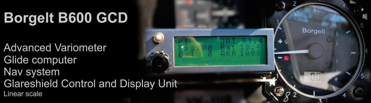
The B600 (linear scale) and B800 (logarithmic scale) Variometers have the same basic vario sensor and functions as the above variometers and the same digital AVERAGER/INTEGRATOR features averager as well as the same audio when climbing in lift.
In addition the B600 and B800 provide a display of RELATIVE NETTO (optionally NETTO) when flying between thermals and a SPEED COMMAND zero reader as well as audio speed command and automatic alerting to lift stronger than the current speed to fly (STF) setting. The Digital averager becomes a NETTO averager making it easy to see if you are flying in rising or sinking air over the last 20 to 30 seconds.
The Borgelt TE probe is of the basic Irving type with modifications.
It should be noted that the pressure change for any given altitude increment reduces with altitude so variometer calibrations require correction for the effects of altitude. The TE probe will automatically compensate for the effects of altitude. Because the air is less dense at altitude which causes the glider polar to change, NETTO, RELATIVE and SPEED COMMAND indications also require correction for altitude. The glider polar also changes with the weight of the glider and with the contamination of the airfoil by insects so both the glider weight and the degradation of the polar due to bugs must be accounted for in the NETTO, RELATIVE and SPEED COMMAND indications. The processing in the BORGELT variometers takes all the relevant effects into account.
Mike Borgelt June 2018